Converting electronic speedo to cable drive
 08-08-2011, 03:30 PM
#1
Registered User
Thread Starter

Join Date: May 2010
Location: Pasco,wa.
Posts: 182
Likes: 0
Received 0 Likes
on
0 Posts
Converting electronic speedo to cable drive
Hey Guys,been having all kinds of issues with my speedometer/odometer.replaced everything I can,used differant speedo heads cant seem to find a sppedo head that works
Everyone sayd they just use a hand held GPS for there speedo and odometer.I dont want to do this,I want one ion the dash that works! that actually looks factory!
Ive hunted allover for info on this and all I can find is a few vague post about,possible useing a 89 or older speedo head and converting the electronic speedo out to cable driven.
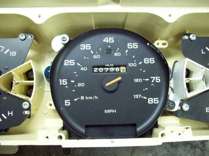
So I went hunting and found me a gauge cluster out of an 82 Dodge truck that I can rob the speedo head out of,picked it up for $30.00...excellant!
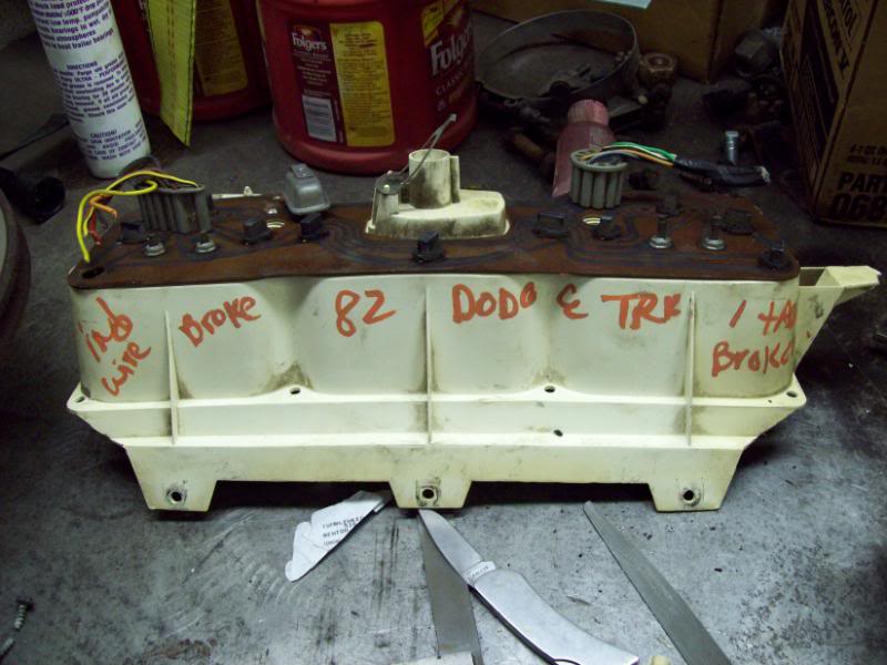
its got a broken needle...I can fix that! All I want is that middle speedo head!
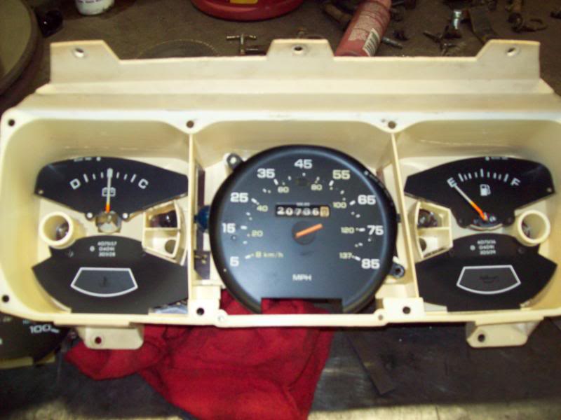
pretty similar to our electronic drive units.
It isnt a diredct bolt in if ya want somthing that lokks factory,but deffinatly doable
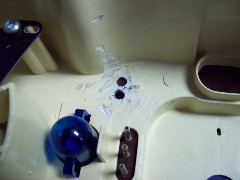
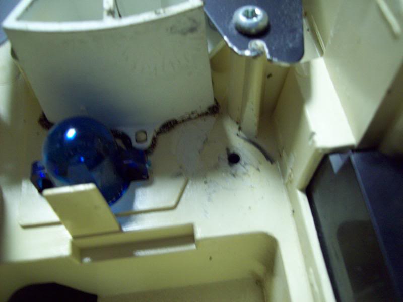
When ya pull out the cable driven unit,theres a rubber grommet on the back side of it where it used to exit the gauge cluster.I figured this is important to battle vibrations,etc from the big ol weight of the spinning head mechanizm.
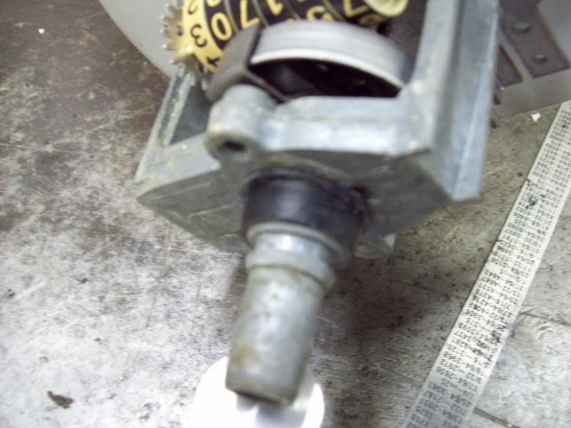
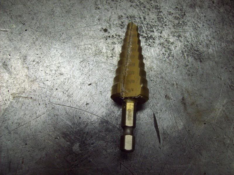
It measure 3/4" so i busted out my trusty uni bits and found my 3/4" these lil guys make nice round holes,unlike drill bits.
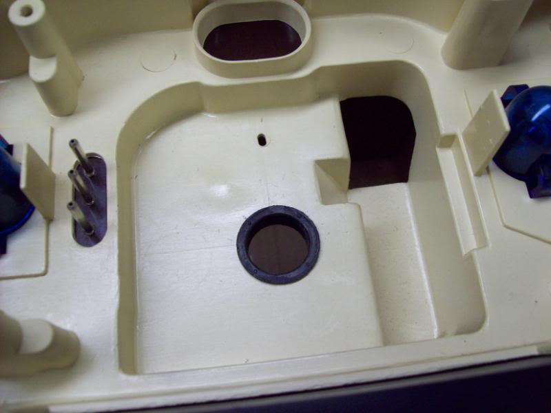
Strategically placed a new hole in the back of my Electronic gauge cluster.
Grommet fits nicely.
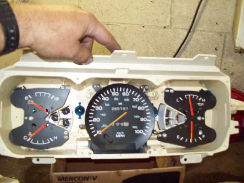
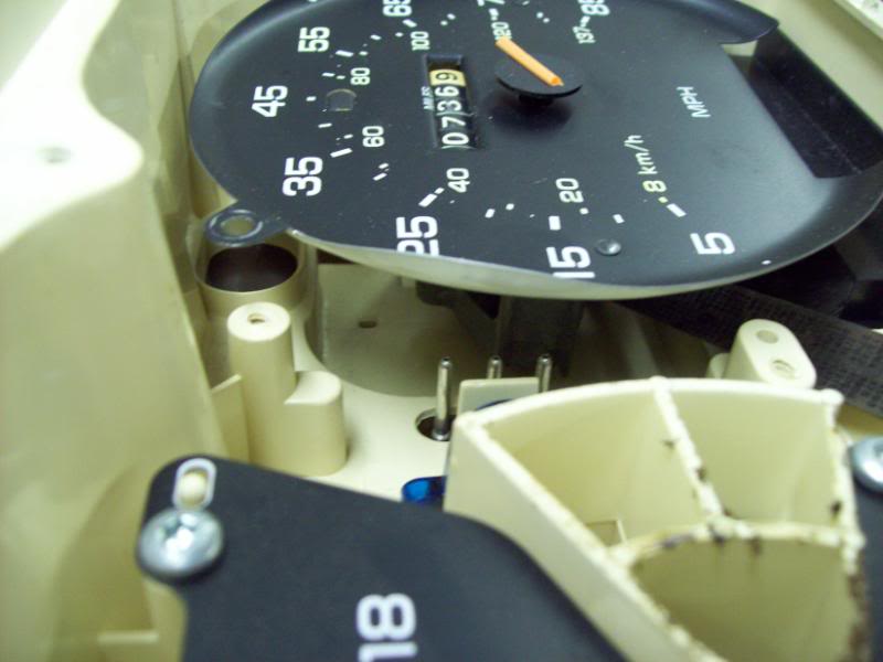
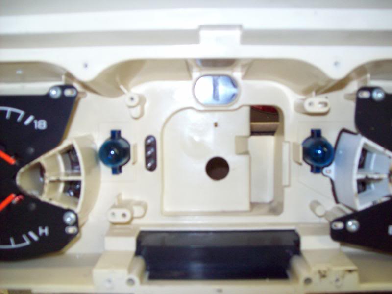
So heres our electronic cluster,with the first modification for the cable drive.Sits in there like so.
The stock stand offs that mount the EDU arent tall enough or quite in the right spot for the new CDU...I knew this wasnt going to be easy.
I think I would have prefered to make some new stand offs out of delrin or somthing nonconductive,but oh well I had some alluminum stock laying around so I cut me some new stand offs 1 22/32" long (this is the perfect heighth where the face plate fits nicely but dosent touch...so no rattles or sqeeks...with any luck.
More to come...
Everyone sayd they just use a hand held GPS for there speedo and odometer.I dont want to do this,I want one ion the dash that works! that actually looks factory!
Ive hunted allover for info on this and all I can find is a few vague post about,possible useing a 89 or older speedo head and converting the electronic speedo out to cable driven.
So I went hunting and found me a gauge cluster out of an 82 Dodge truck that I can rob the speedo head out of,picked it up for $30.00...excellant!
its got a broken needle...I can fix that! All I want is that middle speedo head!
pretty similar to our electronic drive units.
It isnt a diredct bolt in if ya want somthing that lokks factory,but deffinatly doable
When ya pull out the cable driven unit,theres a rubber grommet on the back side of it where it used to exit the gauge cluster.I figured this is important to battle vibrations,etc from the big ol weight of the spinning head mechanizm.
It measure 3/4" so i busted out my trusty uni bits and found my 3/4" these lil guys make nice round holes,unlike drill bits.
Strategically placed a new hole in the back of my Electronic gauge cluster.
Grommet fits nicely.
So heres our electronic cluster,with the first modification for the cable drive.Sits in there like so.
The stock stand offs that mount the EDU arent tall enough or quite in the right spot for the new CDU...I knew this wasnt going to be easy.
I think I would have prefered to make some new stand offs out of delrin or somthing nonconductive,but oh well I had some alluminum stock laying around so I cut me some new stand offs 1 22/32" long (this is the perfect heighth where the face plate fits nicely but dosent touch...so no rattles or sqeeks...with any luck.
More to come...
 08-08-2011, 04:39 PM
#2
Registered User
Thread Starter
Join Date: May 2010
Location: Pasco,wa.
Posts: 182
Likes: 0
Received 0 Likes
on
0 Posts
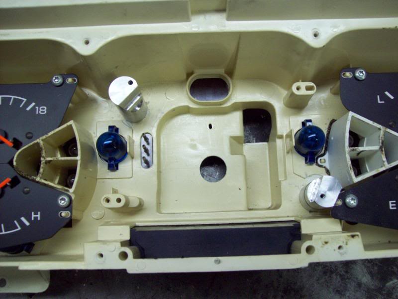
I went ahead and drilled and tapped right in the center for the base of the standoffs.used 3mm screws cause they where handy,again justing useing what I got laying around the shop.
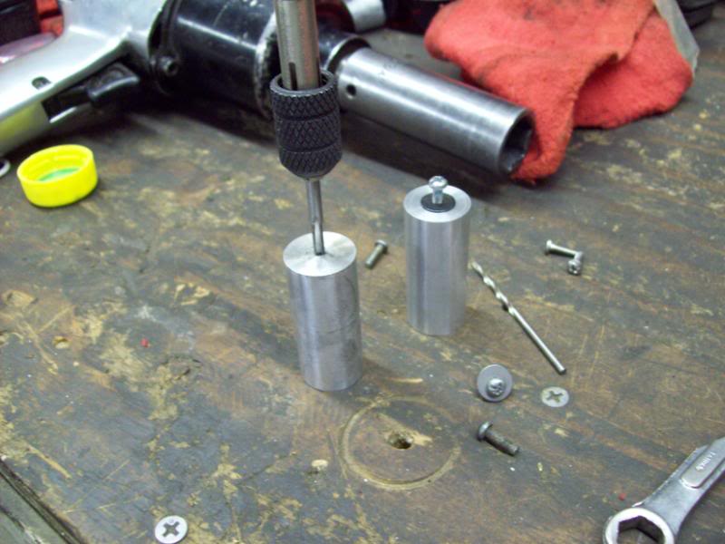
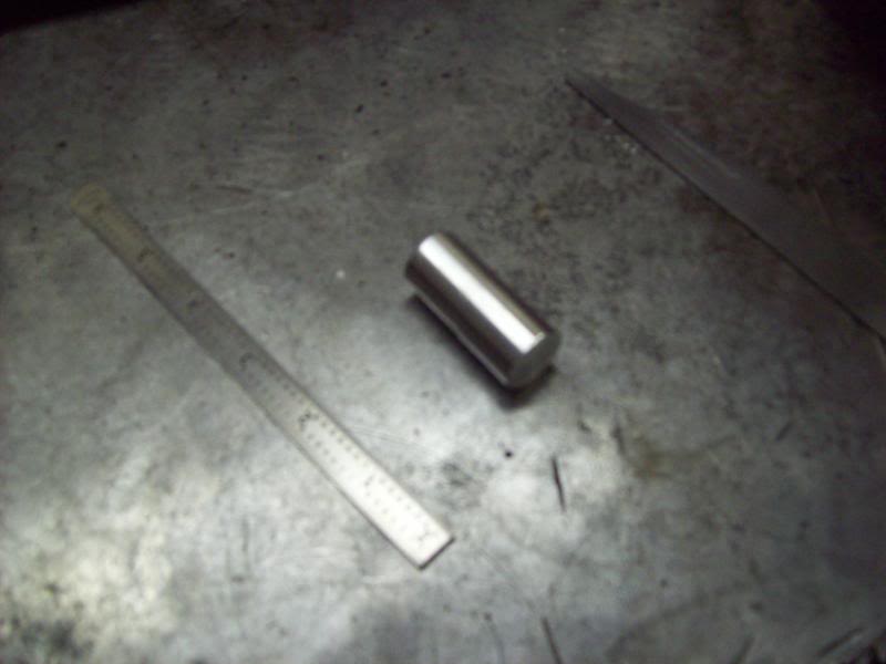
Tis material is about 1" in diam. I figure with the base drilled in the middle that this diam wil be great enough to where the top holes to mount the CDU should hit somewhere out on the edge with enough"meat" to work.
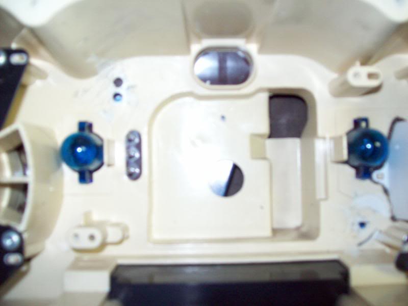
Heres some pics of the EDU cluster with the stock standoffs hacked out of there,I just used a dremel tool,its a lil ruff but actually pretty flat(this is important cause my stand offs are "faced off") I want the stand offs to stand up strait not leaning over.
The factory cluster is molested now lol
Before
After
Now before I did all of this,I did test first
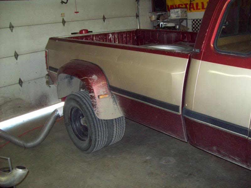
I bought a speedo cable
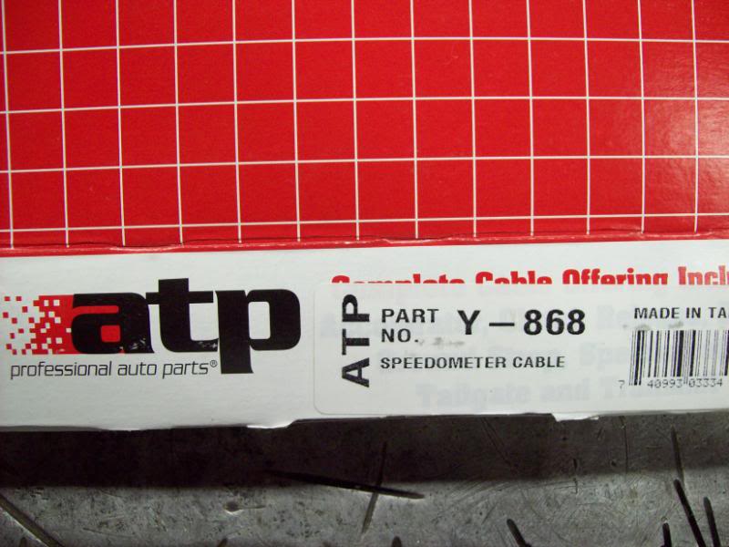
jacked the rig up and routed exhaust outside.
removed the VSS sensor and screwed on the new cable from the 82 Dodge and ran it up to the CDU speedo head and put the rig in 4th and ran up to about 1700 rpm and it read just under 40 mph this is going to work! it spins the right direction and seems "in the ball park" with a "yellow" speedo gear.
Tis material is about 1" in diam. I figure with the base drilled in the middle that this diam wil be great enough to where the top holes to mount the CDU should hit somewhere out on the edge with enough"meat" to work.
Heres some pics of the EDU cluster with the stock standoffs hacked out of there,I just used a dremel tool,its a lil ruff but actually pretty flat(this is important cause my stand offs are "faced off") I want the stand offs to stand up strait not leaning over.
The factory cluster is molested now lol
Before
After
Now before I did all of this,I did test first
I bought a speedo cable
jacked the rig up and routed exhaust outside.
removed the VSS sensor and screwed on the new cable from the 82 Dodge and ran it up to the CDU speedo head and put the rig in 4th and ran up to about 1700 rpm and it read just under 40 mph
this is going to work! it spins the right direction and seems "in the ball park" with a "yellow" speedo gear.
08-08-2011, 04:40 PM
#3
Registered User
Thread Starter
Join Date: May 2010
Location: Pasco,wa.
Posts: 182
Likes: 0
Received 0 Likes
on
0 Posts
back to the good stuff.
I robbed the needle off my EDU.
seperated it from the doohicky and removed the lil tabs so it would be smooth on the bottom for a super glue job on the CDU.
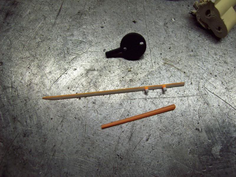
ready to be glued
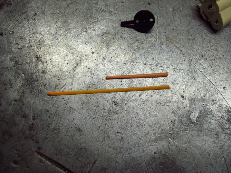
I just used my pocket knife to remove these needle pointers,gently rocking motion and they pop right off.
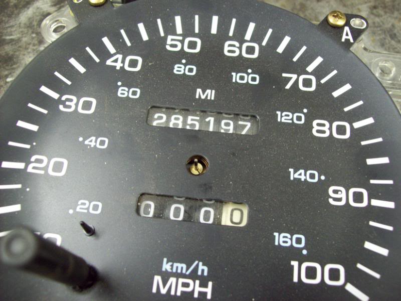
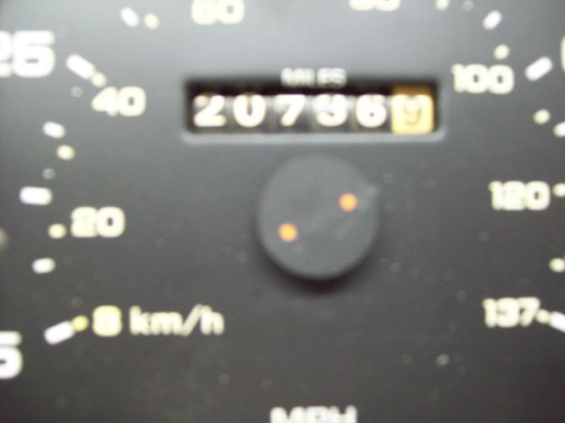
Notice my truck gots much lower miliage on it now lol...not a big deal I dont plan on ever selling this truck I gots way to much time and money in it...besides I LIKE IT.
I robbed the needle off my EDU.
seperated it from the doohicky and removed the lil tabs so it would be smooth on the bottom for a super glue job on the CDU.
ready to be glued
I just used my pocket knife to remove these needle pointers,gently rocking motion and they pop right off.
Notice my truck gots much lower miliage on it now lol...not a big deal I dont plan on ever selling this truck I gots way to much time and money in it...besides I LIKE IT.
08-08-2011, 04:56 PM
#4
Registered User
Thread Starter
Join Date: May 2010
Location: Pasco,wa.
Posts: 182
Likes: 0
Received 0 Likes
on
0 Posts
Heres the new standoffs mounted,I cut some reliefs in them to make clearnace where needed.
Now you can see how the upper holes are so offset from center,this is why I couldnt just extend the stock standoffs,the CDU wouldnt be centered and look hokey.
Heres the CDU mounted in there.
Wah La looks pretty **** factory!
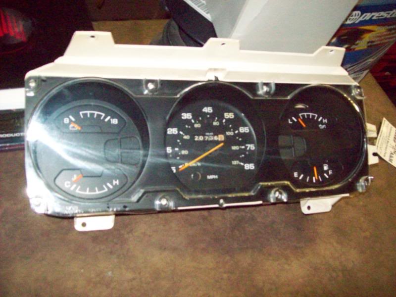
Now I just got to get the cable through the fire wall on the truck,and rig up the retainer on the backside of the cluster to hold in the speedo cable and pull my original unit out and install this one (the cluster Ive been modifieing is a spare I had)
Then a test run with a GPS for a clue to calibration
Ill report back when I get it finished up.
Now you can see how the upper holes are so offset from center,this is why I couldnt just extend the stock standoffs,the CDU wouldnt be centered and look hokey.
Heres the CDU mounted in there.
Wah La looks pretty **** factory!
Now I just got to get the cable through the fire wall on the truck,and rig up the retainer on the backside of the cluster to hold in the speedo cable and pull my original unit out and install this one (the cluster Ive been modifieing is a spare I had)
Then a test run with a GPS for a clue to calibration
Ill report back when I get it finished up.
08-08-2011, 08:06 PM
#5
Registered User

Join Date: Feb 2011
Location: Washington
Posts: 606
Likes: 0
Received 0 Likes
on
0 Posts
Nice to see it will work out. Question: did you not care about having cruise control or did your truck not have it? Just curious as the computer requires the input for cruise.
08-09-2011, 10:40 AM
#6
Registered User
Thread Starter
Join Date: May 2010
Location: Pasco,wa.
Posts: 182
Likes: 0
Received 0 Likes
on
0 Posts
Ive learned so much from the site and the members here,just wanted to give back and share.
08-09-2011, 10:44 AM
#7
Registered User
Thread Starter
Join Date: May 2010
Location: Pasco,wa.
Posts: 182
Likes: 0
Received 0 Likes
on
0 Posts
I put it all togther last night and went for a test drive,the needle was bouncing and sticking a bit.Then I realized I forgot to lube the **** cable
So I brought back into the shop and shot some Royal purple gun oil down the cable( all I had at the moment and it was late) that helped out, but still the needle was sticking a bit.
Took a better look at it this morning,looks like I could do a better job of routing the cable and I got some good quality all weather lube for the cable.So Ill clean up the cable and lube it real good,when I get home tonight Ill get that "S" out of the cable and see if that works better.
It saint easy beeing cheesy
Trending Topics
08-09-2011, 11:25 AM
#8
Registered User
Join Date: Nov 2005
Location: COVINGTON,LA
Posts: 174
Likes: 0
Received 0 Likes
on
0 Posts
some mid 90's dakotas had manual speedos and digital ecm input. the speed sensor on the trans has both outputs. if you want a manual speedo but still want the computer to recieve input you could use one of those
daryl
daryl
08-09-2011, 12:18 PM
#9
Registered User
Join Date: Feb 2011
Location: Washington
Posts: 606
Likes: 0
Received 0 Likes
on
0 Posts
I wonder if the pin configuration is the same and the signal will work for cruise on the 1st gens?
08-09-2011, 02:03 PM
#10
Registered User
Thread Starter
Join Date: May 2010
Location: Pasco,wa.
Posts: 182
Likes: 0
Received 0 Likes
on
0 Posts
I havnt a clue,maybe somone who knows will chime in.I could always upgrade and go that route if I wanted the cruise...honestly ill be pretty **** content to have the a/c working.
08-09-2011, 07:15 PM
#11
Registered User
WOW! I went the other way on my 85 Crew Cab. Changed the whole cluser over to a 93 electronic cluster. Nice stepper motor gauges and the speedo is rock solid and steady, and accurate!
08-11-2011, 10:38 AM
#12
Registered User
Thread Starter
Join Date: May 2010
Location: Pasco,wa.
Posts: 182
Likes: 0
Received 0 Likes
on
0 Posts
I do mechanical so much better than I do electroniclol
Thats why I went this route,cause I can do this! I enjoy fabbing and building of stuff.Im posting this so others can have an idea what it takes and what they can possible expect.
So I simply drilled a few holes in the back of the cluster to hold the clip(the cable retainer) you see in the first pic.
The test run proved a problem,the needle would get stuck on 35 mph eventually it would pop loose and jump up to 45 mph or whatever speed I was going.It did this slowing down also hmmm.
last night I tore it apart and found that the drom on the back of the speedo head was just barely touching the ododmeter drum...so I simply placed a flat blade screw driver in there and pried just a lil and bent the mounting arm for the ododmeter drum for clearance.
test drive: The speedo works perfect now! well almost perfect hehe useing my Delphi gps when my speedo says 25mph Delphi says 22 mph when my speedo reads 45mph delphi read 42 mph when my speedo reads 75 mph delphi reads 72 mph NICE! im reading 3 mph faster than im actually going,not so bad and it very concistent
Super stoked on having a functioning speedo and odometer...finally and if I ever have issues with it,it will be very easy to figure out!
Ill get some pics of how I routed the cable and brought it through the fire wall if anyone interested in that detail.I rerouted the vaccum line to the brake booster and removed the C.C. diaphram thing so i could get a nice arc on the cable coming through the firewall.
lolThats why I went this route,cause I can do this! I enjoy fabbing and building of stuff.Im posting this so others can have an idea what it takes and what they can possible expect.
So I simply drilled a few holes in the back of the cluster to hold the clip(the cable retainer) you see in the first pic.
The test run proved a problem,the needle would get stuck on 35 mph eventually it would pop loose and jump up to 45 mph or whatever speed I was going.It did this slowing down also hmmm.
last night I tore it apart and found that the drom on the back of the speedo head was just barely touching the ododmeter drum...so I simply placed a flat blade screw driver in there and pried just a lil and bent the mounting arm for the ododmeter drum for clearance.
test drive: The speedo works perfect now! well almost perfect hehe useing my Delphi gps when my speedo says 25mph Delphi says 22 mph when my speedo reads 45mph delphi read 42 mph when my speedo reads 75 mph delphi reads 72 mph NICE! im reading 3 mph faster than im actually going,not so bad and it very concistent
Super stoked on having a functioning speedo and odometer...finally and if I ever have issues with it,it will be very easy to figure out!
Ill get some pics of how I routed the cable and brought it through the fire wall if anyone interested in that detail.I rerouted the vaccum line to the brake booster and removed the C.C. diaphram thing so i could get a nice arc on the cable coming through the firewall.
 08-12-2011, 12:41 PM
#15
Registered User
Thread Starter
Join Date: May 2010
Location: Pasco,wa.
Posts: 182
Likes: 0
Received 0 Likes
on
0 Posts
Thanks man!
I found it interesting that the stock set up on the 93's trans converted to the cable drive is that close to the correct mph...pretty cool I think thats close enough no need to spend more money on speedo gears.The dealer told me the speedo gears are like $70.00+ each YIKES! Im sure theres some other outfits you could get the gears through incase a guy wanted it spot on for the reading.
Im just real pleased everything Ive done to the truck has come out positive,I feel like I got me a real nice 1 st gen now...she just needs a new paint job and it will be delux!
I found it interesting that the stock set up on the 93's trans converted to the cable drive is that close to the correct mph...pretty cool I think thats close enough no need to spend more money on speedo gears.The dealer told me the speedo gears are like $70.00+ each
YIKES! Im sure theres some other outfits you could get the gears through incase a guy wanted it spot on for the reading.Im just real pleased everything Ive done to the truck has come out positive,I feel like I got me a real nice 1 st gen now...she just needs a new paint job and it will be delux!