89' Tachometer install
 11-20-2014, 07:59 PM
#1
Registered User
Thread Starter
89' Tachometer install
Ok, started by reading the sticky's and there is a ton of information, but I didn't find where anyone has done what I want to do so I'll start a thread that covers these specific things.
So this is what I want to do and I'll try to explain how I intend to achieve my goals. I fully realize there are many ways to do things and my approach is only one of them.
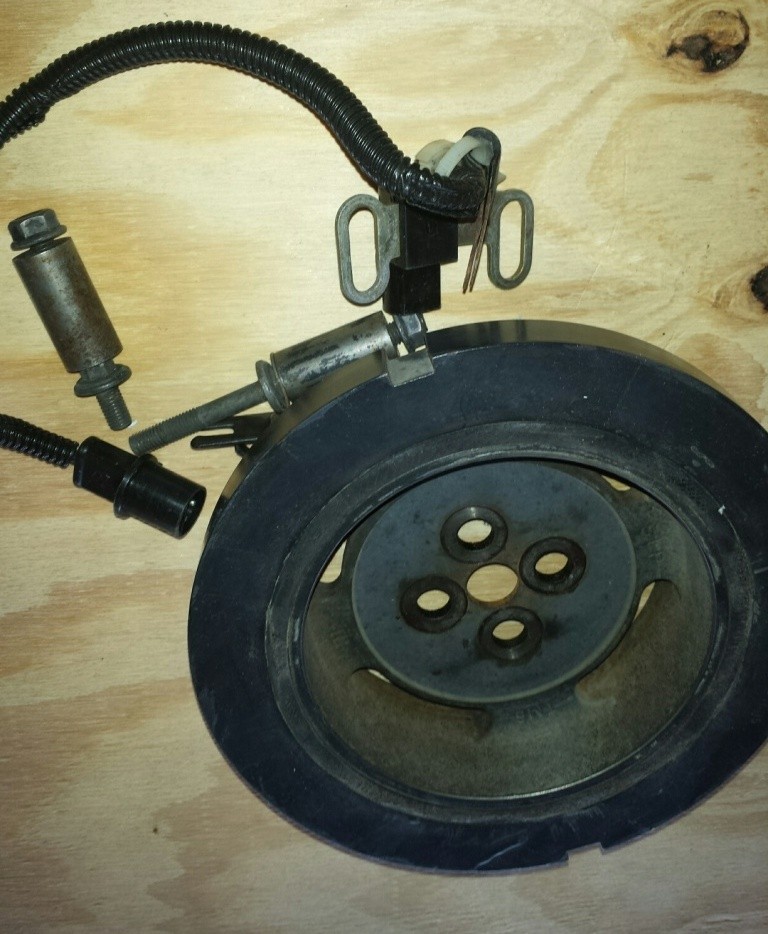
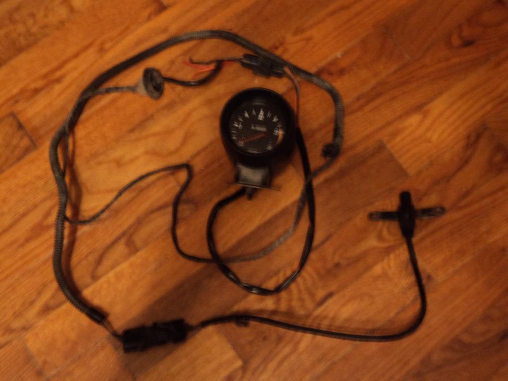
I want to use the Stewart Warner Deluxe Series Tachometers 82620 0-3500 rpm. I feel this has the look and function I like. Plus it has a dip switch that can be set for 2ppr which would support the stock OEM harmonic balancer of a 90.5-93. This harmonic balancer is held on by four bolts and is interchangeable with the 89 balancer. This would then allow the use of the Cummins pickup and bracket. Two knowledgeable forum members have posted that the sensor is excited by 8vdc and this can be supplied by a 12vdc supply using a 8.2 vdc zener diode (1 watt) and a 300 ohm (1/2 watt) resistor. These are readily available although my local RS doesn't carry components any longer. If that works out to be too difficult I could switch the pickup for this one that actually is the recommended pickup, but that would make everything way too easy as I wouldn't need to mess with the zener and resistor. (Stewart Warner Performance Replacement Senders 82646)
I have a 90.5-93 balancer on the way and I may just go ahead and cut some more grooves in it before installing it. (option)
As for mounting, I want to use a cup and mount it in the corner of the dash on the pillar.
I'll continue to post up results as reality intervenes. As a added note the egr and boost gauges I'm thinking of installing in the dash itself.
Thanks, inputs are always appreciated.
So this is what I want to do and I'll try to explain how I intend to achieve my goals. I fully realize there are many ways to do things and my approach is only one of them.
I want to use the Stewart Warner Deluxe Series Tachometers 82620 0-3500 rpm. I feel this has the look and function I like. Plus it has a dip switch that can be set for 2ppr which would support the stock OEM harmonic balancer of a 90.5-93. This harmonic balancer is held on by four bolts and is interchangeable with the 89 balancer. This would then allow the use of the Cummins pickup and bracket. Two knowledgeable forum members have posted that the sensor is excited by 8vdc and this can be supplied by a 12vdc supply using a 8.2 vdc zener diode (1 watt) and a 300 ohm (1/2 watt) resistor. These are readily available although my local RS doesn't carry components any longer. If that works out to be too difficult I could switch the pickup for this one that actually is the recommended pickup, but that would make everything way too easy as I wouldn't need to mess with the zener and resistor. (Stewart Warner Performance Replacement Senders 82646)
I have a 90.5-93 balancer on the way and I may just go ahead and cut some more grooves in it before installing it. (option)
As for mounting, I want to use a cup and mount it in the corner of the dash on the pillar.
I'll continue to post up results as reality intervenes. As a added note the egr and boost gauges I'm thinking of installing in the dash itself.
Thanks, inputs are always appreciated.

 11-24-2014, 12:46 PM
#3
Registered User

Join Date: Jul 2014
Posts: 19
Likes: 0
Received 0 Likes
on
0 Posts
I bought a tach a while back off a 1990. My truck is a 1993, so it's different in the way it picks up its signal. I'm looking forward to how all this goes together, sounds like you have it figured out.

Trending Topics
11-26-2014, 03:00 PM
#8
Registered User
Thread Starter
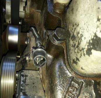
Installed the notched harmonic balancer today. It was a bit of a PIA had to remove the fan and the bolts are torqued to 92 ft/lbs. Someone mentioned the belt pulley was smaller, but I did not find this to be true with the parts I used.

12-01-2014, 08:36 PM
#11
Registered User
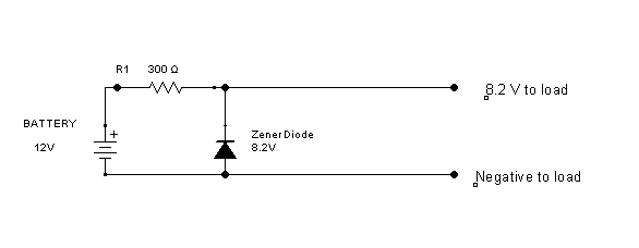
Here's the diagram you asked for. There's a band on the zener diode. It denotes the cathode and goes to the top in the diagram.
300 ohms will supply from 0 to 13 ma to your sensor. If the voltage is low, use a lower value resistor. This should work, though.
300 ohms will supply from 0 to 13 ma to your sensor. If the voltage is low, use a lower value resistor. This should work, though.
12-01-2014, 09:30 PM
#13
Registered User
The Zener voltage is nominal. It can vary by 5% or so.
Don't try to fine tune the voltage with resistors. The zener is what you get, live with it.
12-02-2014, 08:38 AM
#14
Registered User
Thread Starter
The voltage is pinned by the zener diode. It bypasses current not used by the circuit to maintain the voltage at 8.2V. 300 ohms disipates about 0.055 watts. About .1 watt is distributed between the zener and the load. If there's more load than that, the voltage will drop below the zener voltage and cease to be regulated.
The Zener voltage is nominal. It can vary by 5% or so.
Don't try to fine tune the voltage with resistors. The zener is what you get, live with it.
The Zener voltage is nominal. It can vary by 5% or so.
Don't try to fine tune the voltage with resistors. The zener is what you get, live with it.
Thanks,